
ISO 9001:2015 Certified  |  38+ years of power engineering for critical infrastructure
Technical Sizing & Procurement Masterclass

Industrial Battery Chargers: Engineering High-Reliability DC Systems for Critical Infrastructure

An expert technical breakdown covering SCR thyristor vs switch-mode topologies, lithium & NiCd charging curves, SCADA integration via DNP3/Modbus, and long-lifecycle DC power sizing for utility substations, defence, and industrial processing.

  • 38+ Years Power Engineering
  • ISO 9001:2015 Certified Manufacturing
  • AU · NZ · SG · UAE Regional Engineering Hubs
Helios Priority Programme – prioritised technical support for industrial battery chargers

Enterprise Support: The Helios Priority Programme

Substations, mining sites, telecommunication hubs, and process plants cannot afford power interruptions. Under the Helios Priority Programme, asset owners standardising on our industrial battery chargers receive dedicated application engineering support, guaranteed spare parts locking, emergency stock allocation, and annual battery bank health verification across Australia, New Zealand, Asia, and the Middle East.

Send an Inquiry
0Systems Deployed
0Years Field Proven
ISO9001Certified Quality
4Global Engineering Hubs
Engineering Insights & Search Intent Mining

What Defines a True Industrial Battery Charger?

Unlike standard commercial power units, an Industrial Battery Charger is an engineered DC power conversion system designed for continuous 24/7/365 operation under harsh electrical, thermal, and mechanical conditions. It supplies critical direct current (DC) power to continuous loads while simultaneously maintaining standby battery banks (VRLA, Flooded Lead-Acid, Nickel-Cadmium, or LiFePO₄) in a fully charged state.

Key Design Differences: Industrial vs. Commercial Chargers

Global procurement teams and electrical consulting engineers frequently evaluate industrial battery chargers based on dynamic response, isolation barrier rating, short-circuit immunity, and harmonic distortion (THDi). Industrial chargers are custom-engineered for environments where power failure can lead to catastrophic grid breakdown, plant shutdown, or severe safety hazards.

  • Galvanic Isolation: Heavy-duty input and output isolation transformers protect sensitive control electronics and SCADA interfaces from severe grid surges and lightning strikes.
  • Precise Float & Boost Control: Multi-stage charging profiles with automated temperature compensation maintain exact float voltages, preventing thermal runaway in valve-regulated lead-acid (VRLA) cells and memory effects in Nickel-Cadmium (NiCd) batteries.
  • Low AC Ripple Voltage: Filtered output (<2% RMS without battery connected) ensures clean power to protective relays, switchgear trip coils, and sensitive instrumentation without causing electrolyte heating or premature battery degradation.
  • High Mean Time Between Failures (MTBF): Industrial-grade components rated for extended ambient temperature ranges (-20°C to +55°C) without immediate derating.
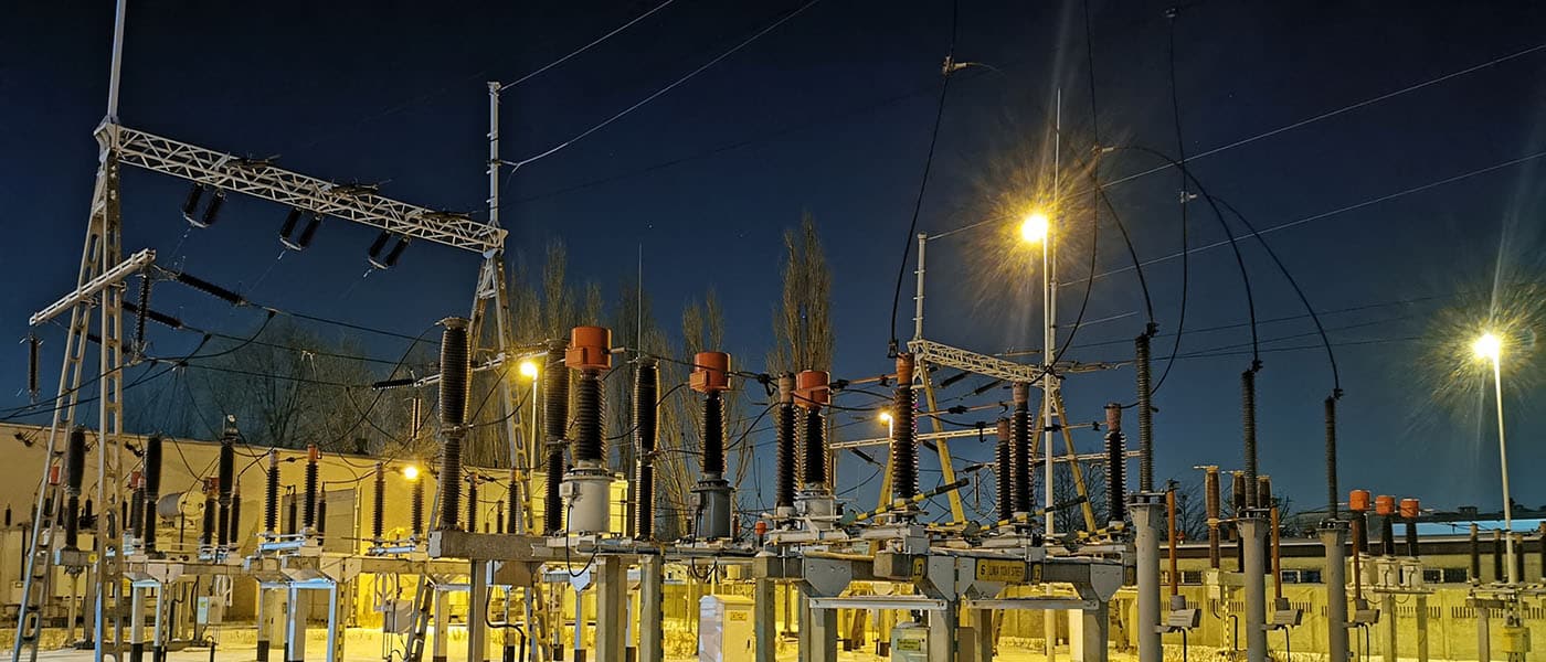
Substation industrial battery charger installation by Helios Power Solutions
Information Gain: Architecture Deep-Dive

Thyristor (SCR) vs. High-Frequency Switch-Mode (HFSM) Chargers

Choosing between silicon-controlled rectifier (SCR) thyristor technology and high-frequency switched-mode power supplies (SMPS) is one of the most critical decisions for utility substation and industrial site engineers.

Detailed Technical Comparison of Industrial Battery Charger Topologies
Parameter / Feature SCR / Thyristor Phase-Controlled Chargers High-Frequency Switch-Mode (HFSM) Chargers
Core Technology Low-frequency (50/60Hz) heavy mains transformer + SCR bridge topology Active Power Factor Correction (PFC) + high-frequency PWM switching (>50kHz)
Electrical Efficiency 80% – 88% (varies with load percentage) 93% – 96.5% (high efficiency across 30%–100% load range)
Input Power Factor 0.70 to 0.85 lagging (requires power factor correction under low loads) > 0.99 at full load with low THDi (< 5%)
Dynamic Response Time 100ms – 200ms recovery time for 10%–90% step load change < 2ms fast recovery for sudden trip coil or switchgear closing currents
Physical Footprint & Weight Large cabinet footprint, heavy magnetic components and transformers Compact, modular 19-inch rack-mount shelves, lightweight modules
Redundancy & MTTR Monolithic cabinet configuration; repair requires technician site visit (MTTR: hours) Modular N+1 hot-swappable shelf designs; module replacement in < 5 minutes (MTTR: minutes)
Ideal Industry Applications Heavy power utilities (110V/220V switchgear), oil & gas refineries, hydro dams Telecom exchanges, remote RTU cabinets, datacentres, modular microgrids
Engineered Solutions

Recommended Industrial Battery Chargers & Systems

Helios Power Solutions manufactures and integrates catalogue platforms, modular systems, and custom engineered-to-order battery charger cabinets optimized for demanding global environments.

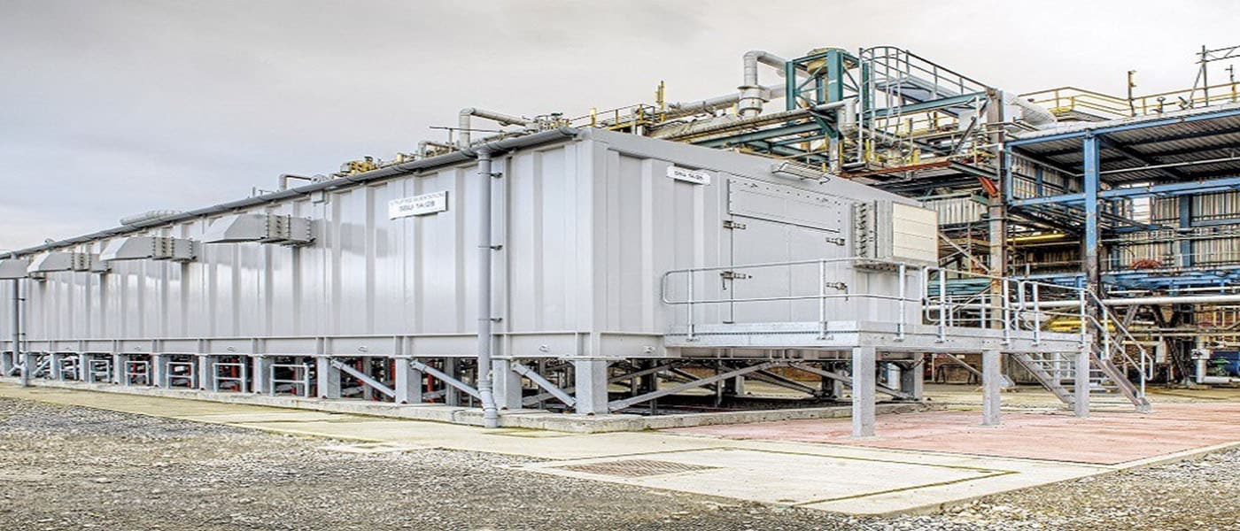
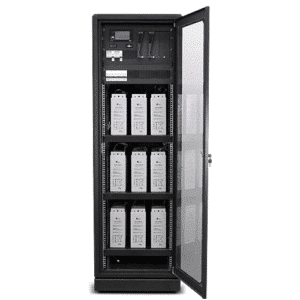
Modular DC System Helios Sol Series Convection Cooled Industrial Battery Charger System

Sol Series Modular Convection-Cooled Charger

Built for dusty and harsh industrial sites where forced-air fan cooling leads to premature failure. Features convection-cooled high-efficiency rectifiers, hot-swappable N+1 redundancy, smart battery management, and DNP3/Modbus telemetry.

Output: 24V, 48V, 110V, 220V DC | Efficiency: 95%
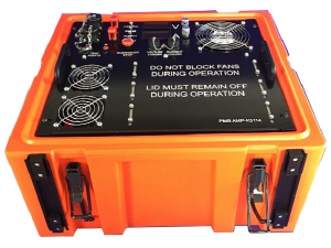
Heavy Duty / Portable AMP-K5114 Portable 7kW 3-Phase Heavy Duty Industrial Charger

AMP-K5114 Portable 7kW Rugged 3-Phase Charger

Designed for field maintenance crews, mining equipment, and deployable defence platforms. Features 3-phase universal AC input, IP65 ruggedized casing, wide operating temperature performance, and automatic multi-stage charging algorithms.

Rating: 7kW Output | Ruggedized & Weatherproof

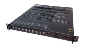
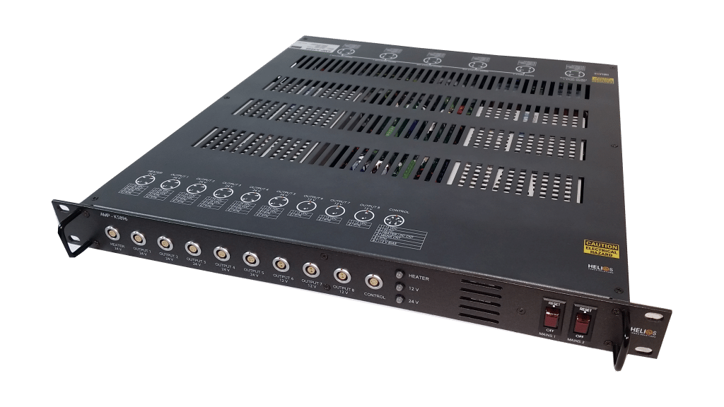
Defence & Rugged AMP-K5896 Multi-Output Military Grade Charger and Power Distribution Unit

AMP-K5896 Military-Grade Multi-Output Power Charger

Engineered to defense specifications (MIL-STD-810G vibration/shock and MIL-STD-461 EMC). Delivers independent multi-channel regulated outputs with integrated battery backup management for mobile control units and naval vessels.

1U Low Profile | MIL-STD Hardened | Custom Comms

Custom Engineered Industrial Charger and DC Distribution Board by Helios Over 50% of systems shipped are engineered to custom client specifications
Custom Engineering Excellence

Tailored Industrial Chargers for Complex Site Conditions

No two utility substations or processing plants share identical site requirements. At Helios Power Solutions, our senior application engineers custom-design DC charger systems that seamlessly adapt to your electrical infrastructure, enclosure constraints, and communication networks.

  • Voltage & Current Customization: Standard nominal outputs (12V, 24V, 48V, 110V, 125V, 220V, 400V DC) tailored to exact load curves and autonomy requirements.
  • Advanced Battery Compatibility: Factory-preset charging profiles for Lead-Acid (VRLA, AGM, Gel, Tubular), Nickel-Cadmium (Pocket Plate & Sintered), and Lithium Iron Phosphate (LiFePO₄) battery banks with BMS integration.
  • SCADA Telemetry & Cyber-Resilient Protocol Mapping: Integrated outstations supporting DNP3 (serial & Ethernet TCP/IP), Modbus RTU/TCP, SNMPv3, and isolated dry contact relay alarms.
  • Environmental Toughening: Conformal-coated PCBs, stainless steel or seismic-rated NEMA/IP enclosures, tropicalization treatments, and anti-vibration shock mounting.
Market Intelligence & Horizon Planning

Future Procurement & Technological Trends in Industrial Battery Chargers

Global procurement managers and power engineers must prepare for major technological shifts taking place across the critical DC power landscape over the next decade.

1. Transition to Lithium Iron Phosphate (LiFePO₄) & Hybrid Battery Chemistries

While flooded NiCd and VRLA batteries remain substation mainstays due to their proven longevity, industrial procurement is rapidly shifting toward LiFePO₄. Modern industrial battery chargers are incorporating active digital communication links (CAN-bus, Modbus) directly with Battery Management Systems (BMS). This allows real-time cell-level voltage monitoring, dynamic current limit adjustments, and instant isolation during thermal anomalies.

2. High-Efficiency Wide Bandgap Semiconductors (SiC & GaN)

Silicon Carbide (SiC) and Gallium Nitride (GaN) power devices are transforming industrial switched-mode rectifiers. Wide-bandgap devices allow higher switching frequencies with significantly lower thermal dissipation. This reduces charger volume by up to 40% while raising operating efficiency above 96.5%, substantially lowering continuous operational expenditure (OPEX) and cooling loads in switchrooms.

3. Predictive Analytics, IoT, and Cyber-Secured SCADA Integration

Future-proof industrial battery chargers are evolving from passive energy converters into intelligent edge nodes. Modern installations require embedded health diagnostics (impedance monitoring, ripple analysis, remaining capacity calculation) delivered securely over SNMPv3 or encrypted DNP3. Remote engineers can now predict battery bank degradation months before a cell fails.

4. Modular N+1 Architectures Replacing Monolithic Cabinets

Legacy monolithic industrial chargers required complete system power-downs during major overhauls. Procurement trends heavily favor hot-swappable modular rectifier architectures. Under an N+1 design, if a single module encounters an internal fault, adjacent modules instantly absorb the load without output voltage fluctuation, dropping Mean Time to Repair (MTTR) to under 5 minutes.

Practical Sizing Methodology

Step-by-Step Technical Sizing Guide for Industrial Battery Chargers

Follow this field-proven engineering methodology to accurately size an industrial charger and avoid common over-sizing or under-charging traps.

The Two Core Functional Sizing Components

An industrial battery charger must satisfy two continuous operating demands simultaneously:

  1. Continuous Standing Load ($I_{load}$): The total steady-state direct current consumed continuously by protective relays, SCADA RTUs, emergency lighting, and control circuits.
  2. Battery Recharge Current ($I_{recharge}$): The current required to restore a fully discharged battery bank back to 90–95% state of charge (SoC) within a specified timeframe (typically 8 to 24 hours according to utility standards IEEE 485 / IEEE 1188).

The Master Sizing Formula

$I_{charger} = I_{load} + \left( \frac{C_{AH} \times K}{T_{recharge}} \right)$

Where:

  • $I_{charger}$: Required total output current rating of the industrial battery charger (Amperes).
  • $I_{load}$: Continuous DC system standing load (Amperes).
  • $C_{AH}$: Total battery bank capacity in Ampere-hours (Ah) at the rated discharge rate.
  • $K$: Battery recharge efficiency factor (typically 1.15 to 1.25 for Lead-Acid; 1.30 to 1.40 for NiCd).
  • $T_{recharge}$: Required recharge time limit in hours (e.g., 10 hours).

Sizing Example: 110V Substation Charger

Site Parameters:

  • Continuous SCADA & Protection Load ($I_{load}$): 25 Amps
  • Station Battery Capacity ($C_{AH}$): 200 Ah VRLA
  • Desired Recharge Window ($T_{recharge}$): 10 Hours
  • Recharge Efficiency Factor ($K$): 1.20

Calculation:

$I_{recharge} = (200 \times 1.20) / 10 = 24 \text{ Amps}$
$I_{charger} = 25 \text{ A (Load)} + 24 \text{ A (Recharge)} = 49 \text{ Amps}$

Recommendation: Select a standard 110V / 50A or 60A Industrial Charger, or a Modular 3x20A (N+1) Rectifier System to guarantee operational redundancy.

Send an Inquiry
Experience, Expertise, Authoritativeness & Trust

Why Enterprise Procurement Teams Trust Helios Power Solutions

For over 38 years, Helios Power Solutions has engineered and delivered high-reliability power systems to blue-chip utilities, defense forces, telecom operators, and heavy industrials across the globe.

38+ Years Heritage

Established in 1987, our senior design engineers bring decades of field-proven power conversion experience to every project.

ISO 9001:2015 Certified

Full quality assurance management across internal engineering design reviews, component selection, thermal testing, and factory acceptance testing (FAT).

4 Strategic Regional Hubs

Local stocking, technical sales, and full field maintenance hubs operating in Sydney (AU), Auckland (NZ), Singapore (SG), and Dubai (UAE).

Lifecycle & Spares Locking

Long-term lifecycle guarantee with committed spare availability and drop-in retrofit options for legacy infrastructure assets.

Send an Inquiry

Proven Field Deployment

Case References: Industrial Chargers in Action

Explore real-world engineering case studies where Helios industrial battery chargers and DC UPS systems safeguard mission-critical operations.

Industrial Charger System at OKI Pulp & Paper Mill

OKI Pulp & Paper Processing Mill

Supplied high-capacity, ruggedized industrial battery chargers to safeguard bark handling and electrical protection systems across one of the largest pulp processing facilities in the world.

Read Full Case Study →
Substation 11kV Switchgear Industrial Charger System

11kV Utility Switchgear Protection

Designed and factory-tested a redundant 110V DC industrial charger system delivering tripping and closing power with automated DNP3 SCADA event telemetry.

Read Full Case Study →
Rugged Hydro Float Chargers in Samoa

Micro-Hydro Station Float Chargers

Delivered 6.2kW heavy-duty float chargers engineered for humid tropical ambient conditions, restoring hydro-turbine lubrication reliability following tropical cyclones.

Read Full Case Study →
Engineering FAQ & Search Intent Solutions

Frequently Asked Questions About Industrial Battery Chargers

Clear, technical answers to common queries asked by plant managers, consulting engineers, and international buyers.

An industrial battery charger is designed specifically to operate safely while directly connected to a battery bank and an active load. It features regulated float/boost charging curves, strict output ripple voltage limits (<2% RMS), reverse-polarity protection, temperature compensation, and galvanic isolation. Standard commercial power supplies lack these specialized battery protection algorithms, leading to overcharging, electrolyte boil-off, or failure during heavy impulse loads such as switchgear tripping.

Send an Inquiry to speak with our application specialists.

AC ripple voltage superimposes high-frequency micro-cycles over the DC output. Excessive ripple (above 2% RMS) causes internal heating within valve-regulated lead-acid (VRLA) and Nickel-Cadmium (NiCd) batteries, accelerating plate corrosion and reducing operational life by up to 50%. Furthermore, low AC ripple is essential to prevent false tripping of sensitive micro-processor protection relays connected to the DC bus.

As ambient temperature rises, battery internal resistance decreases, causing the cell to draw more current at a fixed float voltage—risking thermal runaway. A temperature-compensated charger automatically adjusts float voltage downward (typically -3mV to -5mV per °C per cell) as ambient temperature increases, and upward as temperatures drop. This maintains optimal float charging without overcharging or undercharging.

The standard nominal output voltages for power utilities and substations are 24V DC (small control networks & RTUs), 48V DC (telecommunications & fiber multiplexers), 110V / 125V DC (transmission switchgear, tripping coils & relay logic), and 220V DC (large power generating stations & high-voltage transmission hubs).

Yes. Helios industrial battery chargers feature fully programmable charging stages (Float, Equalize, Boost, and Constant Current / Constant Voltage curves). For NiCd cells, equalizing modes are built-in to prevent memory capacity loss. For Lithium Iron Phosphate (LiFePO₄) banks, our chargers interface directly with the external Battery Management System (BMS) over CAN-bus or Modbus TCP to govern charge parameters dynamically.

Our intelligent system controllers support modern industrial SCADA protocols including DNP3 (Serial & TCP/IP), Modbus RTU / TCP, and SNMPv1/v2c/v3. In addition, user-configurable volt-free (dry contact) relay outputs are provided for hardware alarms such as Mains Fail, Charger Fail, High/Low DC Voltage, and Earth Fault Detection.

In an N+1 modular system, total power capacity is split across multiple hot-swappable rectifier modules plus one additional module. For example, if a 100A requirement is supplied by three 50A modules (150A total capacity), any single module failure will not interrupt the DC bus supply. The faulty module can be swapped by field staff while the system remains fully powered, reducing Mean Time to Repair (MTTR) to minutes.

Industry Technical Directory

Explore Sector-Specific DC Power Architectures

Browse our comprehensive engineering guides tailored to specific industry regulations, standards, and environmental challenges.

Access complete system schematics, fault current calculations, and product datasheets via our engineering portal.

Need a Custom Industrial Battery Charger Specification?

Send our power application engineers your load profile, voltage requirement, and autonomy target for an optimized technical proposal.