
Choosing the right Telecom DC Power Systems in 2026 will require more than comparing price tags and rectifier ratings. Mobile traffic continues to rise as 5G expands, edge computing grows, and operators add power-hungry equipment. Ericsson’s Mobility Report projects mobile data traffic to increase at approximately 16% annually through 2030. GSMA’s Mobile Economy 2025 report also estimates that mobile technologies and services generated 7.6% of global GDP in 2024. These figures expose a practical challenge: telecom power infrastructure must support growth without wasting energy inside every shelter, cabinet, and rooftop site.
Reliability remains the real test. A system may look efficient in a laboratory, yet fail under heat, unstable grids, battery aging, or sudden load changes. Buyers should examine rectifier efficiency, operating voltage, lithium-ion or lead-acid battery performance, remote monitoring, thermal management, and N+1 redundancy. Compliance with relevant requirements, including ETSI EN 300 132-2, should support the technical evaluation rather than replace it. Field experience shows that small design choices matter. A clogged air filter, poor cable sizing, or weak battery monitoring can shorten service life quietly.
That detail is easy to miss.
The best solution will balance uptime, lifecycle cost, maintainability, cybersecurity, and carbon reduction. Operators should also request real operating data, not only laboratory claims. No single architecture fits every network. Rural sites, dense urban locations, and edge facilities face different risks. This guide examines those trade-offs and offers a practical framework for selecting Telecom DC Power Systems in 2026. Some assumptions will need review. Technology changes faster than procurement cycles.
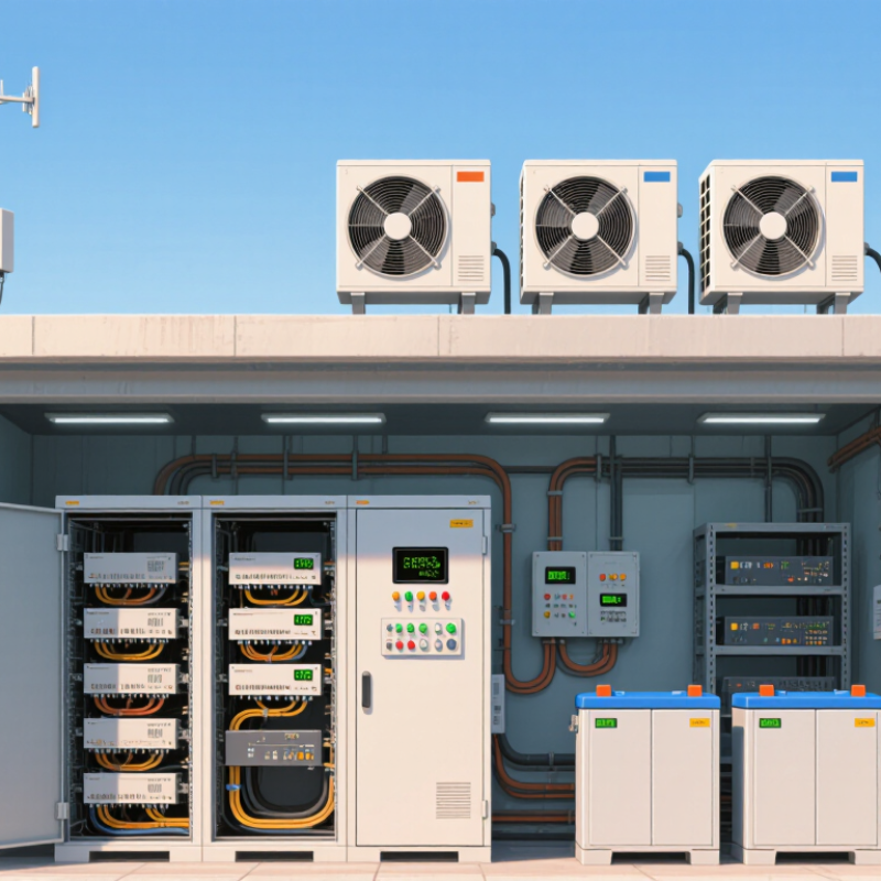
How to Choose the Best Telecom DC Power Systems in 2026?
Define Telecom DC Power System Requirements for 2026
Telecom operators should define power requirements from traffic growth, not current cabinet loads. The Ericsson Mobility Report forecasts mobile data traffic to rise about 20% annually through 2030. That growth will increase rectifier demand, battery cycling, and cooling pressure. A practical 2026 design should support 48V DC distribution, modular rectifiers, remote monitoring, and measured expansion capacity. Avoid sizing only for today’s peak load. It creates expensive limitations later.
Resilience also needs clear numbers. Specify autonomy by site criticality, not by habit. Dense urban sites may need shorter battery support, while remote locations require longer backup periods. The Uptime Institute’s 2024 Global Data Center Survey reported that 54% of respondents experienced outage costs above $100,000. Telecom sites face different conditions, but the lesson remains relevant: test failure scenarios, maintenance bypasses, battery aging, and generator transfer delays. IEC and ETSI guidance can support safer voltage, grounding, and distribution decisions. Still, standards do not replace field measurements. Cable losses are often underestimated.
Tips: Record 24-hour load curves before procurement. Add 20–30% growth headroom, then verify it with traffic forecasts. Check battery performance at low temperatures. Ask for efficiency curves, alarm integration, replacement procedures, and real service records. Some assumptions will be wrong. Revisit them every year.
How to Choose the Best Telecom DC Power Systems in 2026?
Compare Voltage, Capacity, and Modular Architecture Options
Voltage should match the telecom equipment, distribution distance, and site conditions. Most telecom installations use a nominal -48 VDC bus because equipment and protection practices support it. Some compact systems use 24 VDC. Higher distribution voltage can reduce cable losses, but compatibility must come first. A mismatched voltage creates expensive conversion stages and additional failure points. Check the equipment input range, grounding method, and protection settings before selecting the bus.
Capacity requires more than reading an amp-hour label. Measure the normal load, peak demand, battery recharge current, and planned expansion. A practical design should support the present load without running rectifiers near their limits. It should also provide the required backup time during utility failure. Field measurements often reveal uneven cabinet loading. A spreadsheet may miss that. Leave realistic headroom, but avoid excessive oversizing, which increases cost and reduces operating efficiency.
Modular architecture offers useful flexibility. Rectifier modules can be added as demand grows, while an N+1 arrangement keeps service available after one module fails. Hot-swappable units can shorten maintenance work, but only when procedures, connectors, and airflow are properly designed. Inspect module temperature, alarm visibility, battery isolation, and cable routing during commissioning. I have seen well-rated systems underperform because ventilation was overlooked. The design looked complete. The installation was not. Choose a platform that technicians can test safely and expand without rebuilding the entire power room.
A practical comparison of commonly deployed telecom DC power system configurations
| System Profile | Nominal DC Voltage | Typical Rectifier Capacity | Typical Battery Capacity | Rectifier Module Rating | Modular Architecture | Typical Efficiency | Recommended Redundancy | Typical Use Case |
|---|---|---|---|---|---|---|---|---|
| Compact Access System | -48 VDC | 1.5–6 kW | 100–400 Ah | 1.2–3 kW | 1U–3U shelf; hot-swappable modules | Up to 96% | N+1 | Small cellular sites, radio access nodes, fiber access cabinets, and remote network equipment |
| Standard Site Power System | -48 VDC | 6–15 kW | 400–1,200 Ah | 2–3 kW | 4U–8U shelf; expandable rectifier bays | Up to 96% | N+1 or N+2 | Macro cell sites, aggregation points, outdoor cabinets, and regional telecom rooms |
| High-Capacity Central Office System | -48 VDC | 15–60 kW | 1,000–4,000 Ah | 2–3 kW | Multi-shelf parallel architecture with distributed control | Up to 97% | N+2 or higher | Central offices, mobile switching locations, edge data centers, and high-availability network hubs |
| High-Voltage DC Distribution | ±190 to ±400 VDC | 20–120 kW | Capacity engineered by runtime and load profile | 3–10 kW | Scalable power shelves with downstream DC converters | Up to 97% | N+1 or dual bus | Large telecom facilities and data-center environments requiring lower distribution current and reduced cable losses |
| Hybrid DC Power System | -48 VDC with auxiliary DC buses | 5–50 kW | 200–2,000 Ah | 1.2–3 kW | Rectifier, battery, solar, and generator interfaces in one controller | Up to 96% | N+1 for active conversion modules | Off-grid or weak-grid sites where renewable energy, battery storage, and backup generation are combined |
Selection Notes
Reference basis: common telecom engineering practices and typical specifications for modular DC power systems. Values are indicative design ranges rather than manufacturer-specific ratings.
Choosing a telecom DC power system in 2026 requires more than comparing rated output. Efficiency affects operating costs, cabinet temperature, and battery charging time. Measure it under realistic loads, not only at the advertised peak.
Begin with the normal load, growth forecast, and local climate. A system running near its limit may waste energy and recover slowly after an outage. High-efficiency rectifiers help, but ventilation and cable sizing matter too. Plan for heat. In a crowded equipment room, every degree can shorten battery life. I have seen installations perform well on paper but struggle because airflow paths were ignored.
Reliability depends on useful redundancy, clear alarms, and maintainable parts. N+1 capacity can keep services active when one module fails, although it increases initial cost. Backup performance requires more than battery capacity. Check discharge curves, recharge time, aging, temperature compensation, and generator coordination. Test the system with real equipment connected. A brief monthly test may expose weak connections, but it cannot replace deeper capacity testing. Monitoring should show voltage, current, battery health, and alarm history remotely. Keep records. Small inconsistencies often reveal developing faults.
No design is perfect. Forecasts change, and batteries age faster than expected. Review the system annually, then adjust capacity before the site reaches its limits.
A reliable telecom DC power system begins with safety, not price. Confirm protection against overcurrent, short circuits, reverse polarity, and battery faults. Proper grounding and clear isolation points also matter during maintenance. For 48V systems, inspect cable sizing, terminal torque, ventilation, and heat around rectifiers. Small installation errors can create serious downtime.
Standards provide a useful baseline, but certificates alone are not enough. Check compliance with applicable IEC, EN, UL, and local electrical requirements. Request test records for insulation, alarms, battery autonomy, and load performance. During commissioning, measure voltage at distant equipment, not only at the cabinet. Real sites often reveal voltage drops that drawings miss.
Monitoring should display DC voltage, current, temperature, rectifier status, battery health, and active alarms. Remote notifications need clear priorities, or technicians may ignore repeated warnings. A neat dashboard is not proof of resilience. Review event logs and test alarm communication under controlled conditions. Choose modular rectifiers and expandable battery cabinets for future capacity. Leave practical headroom for new network equipment, but avoid buying oversized systems without a load study. Growth forecasts can be wrong. Recheck them annually.
Choosing a telecom DC power system in 2026 starts with the site, not the catalog. A 48V architecture may fit a dense 5G location, while remote sites need simpler thermal and battery designs. GSMA Intelligence’s Mobile Economy 2025 report expects 5G connections to exceed 5.5 billion globally by 2030. That growth increases pressure on power availability, monitoring, and service access.
Select vendors through evidence. Request audited efficiency curves, battery-cycle results, alarm samples, spare-part policies, and local response times. IEC 62477-1 compliance and documented environmental testing should support the evaluation. Calculate total cost across ten years. Include rectifier losses, battery replacement, cooling, transport, installation, software, and technician visits. The IEA’s Electricity 2024 report projects data-centre electricity use could exceed 1,000 TWh by 2026. Telecom sites are smaller, but energy waste still compounds across thousands of locations.
Deployment planning needs a staged cutover. Measure real load for seven days before sizing rectifiers and batteries. Leave growth capacity, but avoid excessive oversizing; it can reduce operating efficiency. Confirm rack weight, cable routes, grounding, ventilation, and generator coordination. Perform an outage simulation before acceptance. Remote alarms should identify low voltage, high temperature, battery imbalance, and rectifier failure. I would not trust a perfect spreadsheet alone. Field conditions often expose missing assumptions. Track actual energy use for ninety days, then revise the cost model and maintenance schedule.
Five-year total cost of ownership for a telecom site with a continuous 10 kW DC load. The comparison includes power equipment, installation, electricity losses, maintenance, and battery replacement.
Planning benchmark in USD thousands. Energy-cost estimates use a 5-year operating period, a 10 kW average load, and an electricity rate of $0.12 per kWh. Actual costs vary by site load, climate, autonomy requirement, utility tariff, and local installation conditions.
Most telecom sites use a nominal -48 VDC bus. Compact installations may use 24 VDC. Match equipment input ranges, grounding, and protection settings. A voltage mismatch adds converters and failure points. Check the entire distribution path.
Measure normal load, peak demand, battery recharge current, and planned expansion. Do not rely only on an amp-hour label. Field measurements can reveal uneven cabinet loading. Leave practical headroom. Excessive capacity raises costs and may reduce efficiency.
Define the required runtime during utility failure. Include current equipment demand and battery recharge needs. Verify actual autonomy during commissioning. Drawings can mislead. Test the distant load, not just the cabinet.
Modular rectifiers can be added as demand increases. An N+1 arrangement keeps service available after one module fails. Hot-swappable units can shorten maintenance. Only use them with suitable connectors, procedures, and airflow.
Confirm protection against overcurrent, short circuits, reverse polarity, and battery faults. Inspect grounding and clear isolation points. Check cable sizing, terminal torque, ventilation, and rectifier heat. Small errors can cause major downtime.
Review applicable international and local electrical requirements. Request records for insulation, alarms, battery autonomy, and load performance. Certificates help, but they are not complete proof. Measure voltage at remote equipment locations.
It should show DC voltage, current, temperature, rectifier status, battery health, and active alarms. Test remote notifications under controlled conditions. Repeated warnings may be ignored. Alarm priorities need clear meaning.
Choose expandable rectifiers and battery cabinets. Leave room for new network equipment and extra cabling. Review growth forecasts annually. They can be wrong. The design may look complete, but ventilation or routing may still fail.
Choosing the best Telecom DC Power Systems in 2026 requires a clear understanding of network demands, site conditions, and long-term growth plans. Start by defining required voltage, load capacity, battery autonomy, redundancy, and environmental operating conditions. Compare centralized and modular architectures, considering installation space, maintenance flexibility, energy efficiency, and the ability to expand capacity without major service interruptions. A suitable system should provide stable DC output, strong backup performance, efficient power conversion, and reliable operation during utility failures.
Safety and compliance are equally important. Evaluate protection features, thermal management, monitoring capabilities, alarm functions, and compatibility with current industry standards. Remote visibility can simplify maintenance and help identify developing issues before they affect network availability. Finally, compare vendors based on technical support, product quality, warranty coverage, lifecycle costs, and deployment experience. By calculating total cost of ownership and creating a phased installation plan, operators can select a scalable, secure, and efficient power solution that supports dependable telecommunications service through 2026 and beyond.